
This project was first published on the earlier BTREE blog. We have tidied it up and republished it here.
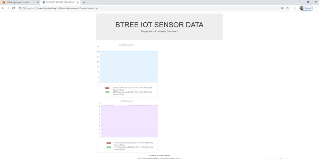
This project captures temperature and humidity from a BTREE IoT sensor, sends the readings to the AWS cloud, stores them in a DynamoDB table, and shows them as live charts on a website. It also controls two relays, one for a cooler and one for a heater, both automatically and manually, based on the sensor readings.
- When the temperature rises above a preset value, the cooler switches on automatically.
- When the humidity rises above a preset value, the heater switches on automatically.
Data flow: NodeMCU + DHT22 → AWS IoT Core (MQTT) → DynamoDB → Node.js → Chart.js → website hosted on AWS S3
See it live
- Live sensor dashboard: btree-iot-dashboard … /index.html
- Live cooler and heater control: btree-iot-dashboard … /cooler.html
The dashboard is protected with an AWS Cognito login page.
What you need
- Hardware: NodeMCU (ESP8266), DHT22 temperature and humidity sensor, 2-channel relay module
- Cloud: an Amazon AWS account (AWS IoT Core, DynamoDB, S3 and Cognito)
- Software: Arduino IDE, OpenSSL, Node.js and Chart.js
- Protocol: MQTT
MQTT (MQ Telemetry Transport) is a simple, lightweight publish/subscribe messaging protocol designed for small devices and low-bandwidth, high-latency or unreliable networks. That makes it a good fit for sensors like this one.
Step 1: Create a Thing in AWS IoT Core
- In AWS IoT Core, create a single Thing and give it a name, for example
btree-iot-sensor. - Click Create certificate, then download:
- the device certificate (
XXXXXXXXXX.cert.pem), used asclient_cert, - the private key (
XXXXXXXXXX.private.key), used asprivkey, - the Amazon Root CA certificate (RSA 2048-bit key), used as
cacert.
- the device certificate (
- Create a policy under Secure → Policies → Create, and attach it to the certificate.
- Note the Thing’s ARN (Amazon Resource Name), which uniquely identifies it. For example:
arn:aws:iot:us-west-2:xxxxxxxxxx:thing/btree-iot-sensor
Keep the certificate files private. Anyone who has them can connect to your AWS account as this device.
Step 2: Convert the certificates to DER format
There are two common ways of encoding certificate data:
- DER: binary encoding of the certificate.
- PEM: the base64 encoding of the DER certificate, with header and footer lines.
The ESP8266 code in this project loads certificates in DER format, so convert them with OpenSSL. On Red Hat-based Linux, install it with yum install openssl. On Ubuntu or Raspberry Pi OS, use sudo apt install openssl. Then run:
openssl x509 -in xxxxxxxxxx-certificate.pem.crt -out cert.der -outform DER
openssl rsa  -in xxxxxxxxxx-private.pem.key  -out private.der -outform DER
openssl x509 -in AmazonRootCA1.pem -out ca.der -outform DER
Upload the three .der files to the NodeMCU’s SPIFFS file system.
Step 3: Connect the NodeMCU to AWS IoT Core
Copy your account’s AWS IoT endpoint, the address of the MQTT broker for your region, from the AWS IoT Core settings, and add it to the Arduino code:
const char* AWS_endpoint = "xxxxxxxxxxxxxx-ats.iot.us-west-2.amazonaws.com"; // MQTT brokerThe DHT22 sensor is connected to GPIO 14 (pin D5) of the NodeMCU:
// GPIO 14 = NodeMCU pin D5: DHT22 temperature and humidity sensor
uint8_t DHTPin = 14;
DHT dht(DHTPin, DHTTYPE);
These are the key parts of the sketch that load the certificates and keep the MQTT connection alive:
// Load the device certificate, private key and CA certificate from SPIFFS
File cert = SPIFFS.open("/cert.der", "r");
if (!cert) Serial.println("Failed to open cert file");
else Serial.println("Success to open cert file");
delay(1000);
if (espClient.loadCertificate(cert)) Serial.println("cert loaded");
else Serial.println("cert not loaded");

File private_key = SPIFFS.open("/private.der", "r");
if (!private_key) Serial.println("Failed to open private cert file");
else Serial.println("Success to open private cert file");
delay(1000);
if (espClient.loadPrivateKey(private_key)) Serial.println("private key loaded");
else Serial.println("private key not loaded");

File ca = SPIFFS.open("/ca.der", "r");
if (!ca) Serial.println("Failed to open ca");
else Serial.println("Success to open ca");
delay(1000);
if (espClient.loadCACert(ca)) Serial.println("ca loaded");
else Serial.println("ca failed");
void reconnect() {
// Loop until we're reconnected
while (!client.connected()) {
Serial.print("Attempting MQTT connection...");
if (client.connect("BTREEHOMERELAYS")) {
Serial.println("connected");
client.publish("my/outTopic", "hello world"); // announce
client.subscribe("my/inTopic"); // listen for relay commands
} else {
Serial.print("failed, rc=");
Serial.print(client.state());
Serial.println(" try again in 5 seconds");
char buf[256];
espClient.getLastSSLError(buf, 256);
Serial.print("WiFiClientSecure SSL error: ");
Serial.println(buf);
delay(5000);
}
}
}The device publishes sensor readings to the topic my/outTopic and listens for cooler and heater commands on my/inTopic.
Step 4: Store the readings in DynamoDB
What is an AWS IoT rule?
An AWS IoT rule has three parts: an SQL SELECT statement, a topic filter and a rule action. Devices send data to AWS IoT by publishing MQTT messages. When a message arrives on a topic that matches the filter, the rule runs. The SELECT statement extracts the data you need, and the action sends it to another AWS service, such as DynamoDB, Lambda, SNS or S3. See the full list of AWS IoT rule actions.
Create the table and the rule
- In DynamoDB, create a table, for example
btree-iot-sensor, with:- partition key
id(string), for the MQTT topic, - sort key
timestamp(number), for the date and time of the reading.
- partition key
- In AWS IoT, go to Act → Rules → Create.
- Use this rule query for the topic
my/outTopic:
SELECT *, timestamp() AS ts FROM 'my/outTopic'- Choose the DynamoDB action and select your table.
Test it
From the MQTT test client in AWS IoT Core, publish a test message to my/outTopic:
{ "mac_Id": "12345", "temperature": "32.50", "humidity": "83.50" }The message should appear as a new item in your DynamoDB table.
Step 5: Live charts and relay control
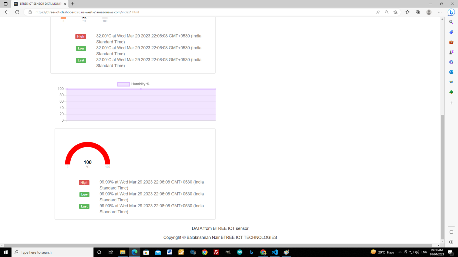
A small Node.js script reads the latest items from DynamoDB, and Chart.js draws them as live temperature and humidity charts, with the high, low and last readings. The web pages are hosted as a static website on AWS S3, behind an AWS Cognito login.
For the cooler and heater, the control page publishes commands to my/inTopic. The NodeMCU switches the relays when it receives a command (manual mode), or by itself when the temperature or humidity crosses its preset limit (automatic mode).
Notes for building this today
This project was built on the ESP8266 Arduino core of the time. Newer versions of the core use a different (BearSSL) API for loading certificates, so if loadCertificate() does not compile, use the client-certificate functions from the current ESP8266 examples instead. The AWS steps remain the same.
Further reading
These two tutorials explain the first steps in more detail:
Want a monitoring and control system like this for a cold room, server room, poultry farm or greenhouse? BTREE designs and builds connected IoT systems. Contact us with your requirement.